BuickGirlFromMars
SUPER STAR!
- Joined
- Oct 8, 2018
- Messages
- 7,961
- Reaction score
- 2,771
- Points
- 113
- Buick Ownership
- 1999 Buick Park Avenue Ultra (Supercharged) , 1977 Buick Electra Limited (350 SBB)
the instrument panel reading is most likely due to corrosion at some connections, I believe the voltage on the DIC is read at the PCM but its possible it was read at the interior fusebox.. i can check if youd like. that just tells me the reading has some corrosion or voltage drops. Its not hurting anything. if you have a scantool, id be curious to know what your PCM voltage is on the various ignition circuits, because they are different, since those are channeled through the BCM and then the PCM voltage which itself is diffferent etc etc.I upgraded my worn out 125A alternator to a 150A Nippondenso:
It is a direct fit, same mounting as the 125 original alternator.
The main connection of the alternator was the same as the old one.
The connector for the control is in a slightly different place, but the cable is just long enough.
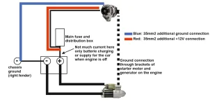
I have laid additional 35mm2 (AWG 2 ?) cables for plus 12V to the fuse box, and case of the alternator to ground to take care of the higher possible current.
This works really well. The alternator is delivering 90-100A even at 1000rpm idle. Voltage is even under heavy load between 14.5V - 14.8V at the batterie, measured with a Fluke DMM. The voltmeter in the instrument panel shows 13.9V when the alternator has 14.8V.
But good work, thanks for the information. The Nippondenso unit I hope is high quality like AD series alternators, GM at least put them on so presumably there was enough quality they would stand behind them for new cars sold.
They are japanese, which is not a dig at all. I think that same company makes the one that goes in my hyundai but i could be wrong, but its a smaller unit. Also the pulley failed not the alternator(i still have the og one)
Where did you ground the case of the alternator too?
and if you want to see if there is something affecting the voltage reading upstream or near the alternator, you can utilize the sense wire and run it to the power feed for the under dash fuse box or maybe to the positive lead into the backseat box. that would overcome any drops between all the connections and maintain proper voltage at the place you used the sense wire at.
also, load management features are always possible to interact with your readings. a tech 2 can turn that off but i would appreciate if you drive some more and report any noticed things or quirks and maybe take a reading here and there in the future under different conditions/loads for good measure 🙂
its okay, I wouldnt want to do homework either lol!
Thank you for your findings
did you update to the 150amp because of the part number I posted earlier or was this your own research?I upgraded my worn out 125A alternator to a 150A Nippondenso:
It is a direct fit, same mounting as the 125 original alternator.
The main connection of the alternator was the same as the old one.
The connector for the control is in a slightly different place, but the cable is just long enough.
I have laid additional 35mm2 (AWG 2 ?) cables for plus 12V to the fuse box, and case of the alternator to ground to take care of the higher possible current.
This works really well. The alternator is delivering 90-100A even at 1000rpm idle. Voltage is even under heavy load between 14.5V - 14.8V at the batterie, measured with a Fluke DMM. The voltmeter in the instrument panel shows 13.9V when the alternator has 14.8V.
Either way, im glad to see
Part# 334-2858 - ACDelco
has worked out 🙂