Lower control arms

ede smith

Member
Joined
Apr 8, 2021
Messages
98
Reaction score
11
Points
8
Buick Ownership
Century
2001 Buick Century
165,000 miles

I ordered Mevotech supreme lower control arms and was reading through the service manual before I replace them.

A couple questions, will an autozone ball joint separator tool rental be adequate?
They recommend using GM tool J41820 and avoiding pry bars.

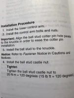
Also on tightening the ball joint stud, will there actually be enough clearance to get a torque wrench in there, or is this gonna be a more by feel thing? 15ft lbs plus 120 degrees doesn’t seem like a lot and I can be heavy handed.

IMG_8139.webp
 
Just an update for those that deal with this. I replaced the drivers side LCA in September and the passenger side a couple nights ago.

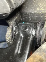
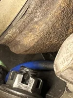
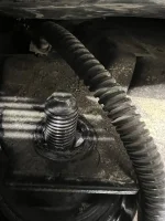
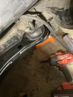
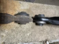
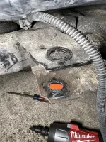
There are 2 through bolts on the frame for the LCA, the front which has a Torx that goes vertically through mounting bracket and the rear bolt that goes parallel with the frame rail. The other point of contact is of course the ball joint stud.

Taking it out is easy enough. The first side must of been loose because I was able to use an air hammer to knock the control arm/ball joint down from the knuckle. The second side I tried using the rental tool from auto zone, it looks like an alligator pincher with a bolt in the center. That tool does not provide enough clearance though. So I resorted to the air hammer again and this time it didn't work despite lots of hammering on the LCA. So, back to autozone and borrowed a ball joint fork, which I wanted to avoid using since the knuckle is aluminum and the fork is steel. It worked so well and should of rented that tool from the get go.

Putting the new LCA back in and getting everything to line up is kind of a PITA. Getting the ball joint lined up first and then routing it to the frame seems to be the best way. I actually re-installed it several times in order to get the stud to seat as I was seeing exposed stud between the control arm and the stud mount.

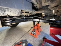
The front mount/bushing is a bear. I tried using a floor jack to lift the control arm on it and it to get the front bushing/mount in place but it was still binding. One would think you would reverse the procedure of removal, secure to frame first then ball joint, but it didn't work getting the ball stud aligned for me that way.

Of course I was doing this on the floor and One thing I noticed is an elongated bolt hole in the front bracket. My plan is to take two grade 8 washer and weld top and bottom while the bolt is still through the bushing.. I am wondering if the bushing which I was told was bad by the person that did my alignment, caused the elongation.

Also, the prior torque spec I posted above, 15 ft/lbs + 120 degrees is probably ends up being at minimum 50 ft/lbs of torque. It's difficult to nail down, I feel like the first one I might of slightly overtorqued and the second one I might give it a little more of a turn. Maybe I need to invest in some Crowfoot wrenches if that would even fit.

I disliked this job even more than doing the FWD bearings but it's done for now.

1763689933700.webp1763689975018.webp
1763689988185.webp1763690048817.webp1763690057598.webp1763690065661.webp1763690075427.webp
 
Excellent details! Thank you. The elongated hole that you well described and photographed located at the front control arm pivot mount, is it your opinion that the front bolt was walking around on either control arm?
 
Excellent details! Thank you. The elongated hole that you well described and photographed located at the front control arm pivot mount, is it your opinion that the front bolt was walking around on either control arm?
Thanks! That is what I am thinking unless they are for alignment. Unfortunately I didn't get a good photo of the mounting hole on the first side to compare the second side to. Maybe someone else will chime in to corroborate.
 
______________________________

Help support this site so it can continue supporting you!
Thanks! That is what I am thinking unless they are for alignment. Unfortunately I didn't get a good photo of the mounting hole on the first side to compare the second side to. Maybe someone else will chime in to corroborate.
That's a really good point. The camber is adjustable at the base of the strut by adding an aftermarket eccentric bolt. But, now that you mention it, caster could be adjusted by sliding either control arm pivot. I'm glad you brought this up because I've always assumed that cater adjustment had gone the way of the dodo.

But, regardless, your point is still very relevant in that the pivot point (once tightened) should never move around. Perhaps adding the grade 8 washers, torque the bolt and mark the location with center punch marks is appropriate? Then when you change your oil, you could have a look to make sure it's stable. But nonetheless, learning it's slotted from your post is most helpful.
 
Back
Top