DrivenDaily
Well-known member
- Joined
- Feb 20, 2024
- Messages
- 773
- Reaction score
- 423
- Points
- 63
- Buick Ownership
- 2005 LeSabre Limited
While it is still a work in progress, I wanted to share part of my journey with replacing and upgrading the lights in the dash, which illuminate the HVAC, headlight controls, and the gauges.
I would have included the radio, but since it is in the process of being replaced, I chose not to change the lighting in it.
ALL of the button and gauge illumination is done with tiny incandescent bulbs, all of which are soldered in place. That's right! No sockets.
The HVAC head unit is the one that gave me the most fits. Its design leaves little or no room to replace the six (6) bulbs with 5 green 3mm LEDs and one white 5mm LED, but that is what I did. Actually, after replacing them, reassembling the control face into the back portion that snaps into the dash was impossible. It lacked about 1/16" (or about 1.5mm) of letting me stuff the repaired control face into the rear cavity, so after about 3-4 hours of repairs and failed attempts to reassemble it, I opted buy one off of Flea Bay. It should arrive this week . . .
The headlight control was the easiest one to do. There are 4 bulbs in it that are even tinier than in the HVAC or gauges, and I was able to replace them with 1.8mm green LEDs in about 2 hours.
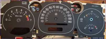
The gauges were my biggest concern since the tach was completely dark, the speedo had only one remaining bulb that lit up the speeds from about 100 to 140, whereas the fuel and coolant temp were fairly well lit.
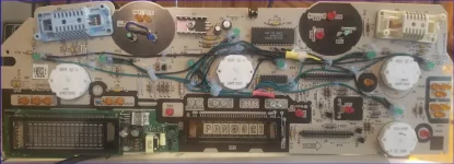
In the image below you can see eight 5mm green LEDs with wires in what looks like a mess. OK, it is, but it works. Those 8 LEDs are for the gauges themselves. There are 3 more bulbs for the turn and high beam indicators inside the black circles at the top of the board. For the high beam I used a 5mm blue LED, and for the turn signals I used 3mm green LEDs. Interestingly, the 3mm LEDs are brighter than the 5mm LEDs! I need to experiment to see if I need to add some ND stickers to reduce the brightness once I add the cover.
Since the original bulbs were soldered in and their bases were attached to the bulbs and not the PC board, I chose to use hot glue to locate them in the same positions, and then route the wires to a convenient spot on the board, cutting the leads and soldering all of the positives together and all of the grounds together. When test-fitting the faces, I found it was necessary to move the group of positive leads, which are protected by a red heat shrink tube. They prevented the plastic shrouds around the stock LEDs from fitting tightly against the board.


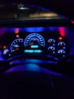
Illumination at night, with the brightness at its lowest level. Clear cover is not installed yet:

I would have included the radio, but since it is in the process of being replaced, I chose not to change the lighting in it.
ALL of the button and gauge illumination is done with tiny incandescent bulbs, all of which are soldered in place. That's right! No sockets.
The HVAC head unit is the one that gave me the most fits. Its design leaves little or no room to replace the six (6) bulbs with 5 green 3mm LEDs and one white 5mm LED, but that is what I did. Actually, after replacing them, reassembling the control face into the back portion that snaps into the dash was impossible. It lacked about 1/16" (or about 1.5mm) of letting me stuff the repaired control face into the rear cavity, so after about 3-4 hours of repairs and failed attempts to reassemble it, I opted buy one off of Flea Bay. It should arrive this week . . .
The headlight control was the easiest one to do. There are 4 bulbs in it that are even tinier than in the HVAC or gauges, and I was able to replace them with 1.8mm green LEDs in about 2 hours.
The gauges were my biggest concern since the tach was completely dark, the speedo had only one remaining bulb that lit up the speeds from about 100 to 140, whereas the fuel and coolant temp were fairly well lit.
In the image below you can see eight 5mm green LEDs with wires in what looks like a mess. OK, it is, but it works. Those 8 LEDs are for the gauges themselves. There are 3 more bulbs for the turn and high beam indicators inside the black circles at the top of the board. For the high beam I used a 5mm blue LED, and for the turn signals I used 3mm green LEDs. Interestingly, the 3mm LEDs are brighter than the 5mm LEDs! I need to experiment to see if I need to add some ND stickers to reduce the brightness once I add the cover.
Since the original bulbs were soldered in and their bases were attached to the bulbs and not the PC board, I chose to use hot glue to locate them in the same positions, and then route the wires to a convenient spot on the board, cutting the leads and soldering all of the positives together and all of the grounds together. When test-fitting the faces, I found it was necessary to move the group of positive leads, which are protected by a red heat shrink tube. They prevented the plastic shrouds around the stock LEDs from fitting tightly against the board.


Illumination at night, with the brightness at its lowest level. Clear cover is not installed yet:


