2014+ Digital Cluster Retrofit in a 2012 Regal GS!!

Does anyone know what the USB port on the back of the GS cluster is used for?

I think its so you can charge an extra controller or plug in the Xbox Kinect Sensor Bar 😉.
 
Ok, where do we get the hud?
 
I'm thinking you already know this but it still won't work (at least for audio controls etc you'll get the cluster menus but thats it)... you are missing everything else on the MOST bus 🙁 I guess if you REALLY want to fabricate the harnesses for the radio/hmi/mdp you could but it will still have missing frames from other modules. There are a TON of software revisions between the silver box cars and the HMI cars...

PS we can also program it properly so you don't have the warning lights from features you don't have 😉


I am well aware. I have been working on a side project for quite some time now. Integrating the full center stack from the new IO6 cars into mine. This involves acquiring the modules, a fully custom harness, control panels, steering wheel, etc. The cluster was just the first of many steps. My main swap harness is almost complete (and I already ran the wires to the cluster for MOST+/- IN MOST+/- OUT and MOST CONTROL 😛 ).

I have the HMI , Radio Module, HVAC, On*, Display/Controls, Disc Player, and antennas complete. I will be working on the final Multi-Button control (Hazard, GS, Parking, etc) this weekend if I have time.

It is by no means a plug and play swap or one for the squeamish. This has involved trial and error along with hours upon hours of studying electrical and data flow diagrams in Service Information System. I have access to a full on electronics lab to properly test, pinout, solder, and fabricate this EXTREMELY complicated harness. This is not at all a project for a weekend warrior with a Radio Shack iron. I have tried to make my harness as clean (using multiple stages of heat shrink and loom) and as plug-and-play as I can with flying leads (with the proper pins to they can be integrated into the factory connectors) only where absolutely necessary. I am waiting on some connectors from Mouser so I can plug into my factory body harness rather than tapping, splicing, or anything of that nature.

This swap involves tapping into and or CREATING data networks inside your car and you must be well versed in how they all work at a physical and datalink layer
MOST - Media Optimized Systems Transport
  • Used for transportation of Audio/Video data between components
  • This is not present on any car that does not have an HMI based infotainment system and will need to be fully fabricated into your harness
  • It is a Ring based topology with every device having D+/D- IN and OUT
  • Being as it is RING based, you also have a control line leading back to a common bus
  • This control line is how the MOST MASTER (in our case the Radio Module) identifies/enumerates devices and controls who is talking when

GMLAN 29 - High Speed two wire Serial Data
  • Used for transportation of High Speed 29-Bit Serial Data (It is CANBus)
  • This does exist in our cars; but not in the radio stack (you will have to steal the lines from the ON* module)
  • This is used for what is considered HIGH PRIORITY data signaling

GMLAN 11 - Low Speed single wire serial Serial Data
  • Used for transportation of Low Speed 11-Bit Serial Data (It is CANBus)
  • This does exist in our cars; and does exist in the radio stack
  • This is used for what is considered Low/Med PRIORITY data signaling

LIN - Local Interconnect Network
  • Used for transportation of control signaling from a host device (a module of some sort) to an input device
  • Great examples are Radio control panel to radio unit or steering wheel controls to gauge cluster

LVDS - Low Voltage Differential Signaling
  • Those "USB" ports...
  • Most of them arent actually USB, they are two wire + shield LVDS connections used for display signaling as GTPprix said
  • These exist in a different form in the earlier regals, but ONLY to drive the primary 7" radio display


I will post pinouts and much more complete information when I complete the retrofit and confirm that it is working.
 

Attachments

  • IMG_5149.webp
    IMG_5149.webp
    111.9 KB · Views: 108
  • IMG_5150.webp
    IMG_5150.webp
    88.2 KB · Views: 94
  • IMG_5151.webp
    IMG_5151.webp
    104.7 KB · Views: 85
  • IMG_5475.webp
    IMG_5475.webp
    97.1 KB · Views: 87
  • IMG_5474.webp
    IMG_5474.webp
    103.8 KB · Views: 85
  • IMG_5473.webp
    IMG_5473.webp
    99.6 KB · Views: 86
I am well aware. I have been working on a side project for quite some time now. Integrating the full center stack from the new IO6 cars into mine. This involves acquiring the modules, a fully custom harness, control panels, steering wheel, etc. The cluster was just the first of many steps. My main swap harness is almost complete (and I already ran the wires to the cluster for MOST+/- IN MOST+/- OUT and MOST CONTROL 😛 ).

I have the HMI , Radio Module, HVAC, On*, Display/Controls, Disc Player, and antennas complete. I will be working on the final Multi-Button control (Hazard, GS, Parking, etc) this weekend if I have time.

It is by no means a plug and play swap or one for the squeamish. This has involved trial and error along with hours upon hours of studying electrical and data flow diagrams in Service Information System. I have access to a full on electronics lab to properly test, pinout, solder, and fabricate this EXTREMELY complicated harness. This is not at all a project for a weekend warrior with a Radio Shack iron. I have tried to make my harness as clean (using multiple stages of heat shrink and loom) and as plug-and-play as I can with flying leads (with the proper pins to they can be integrated into the factory connectors) only where absolutely necessary. I am waiting on some connectors from Mouser so I can plug into my factory body harness rather than tapping, splicing, or anything of that nature.

This swap involves tapping into and or CREATING data networks inside your car and you must be well versed in how they all work at a physical and datalink layer
MOST - Media Optimized Systems Transport
  • Used for transportation of Audio/Video data between components
  • This is not present on any car that does not have an HMI based infotainment system and will need to be fully fabricated into your harness
  • It is a Ring based topology with every device having D+/D- IN and OUT
  • Being as it is RING based, you also have a control line leading back to a common bus
  • This control line is how the MOST MASTER (in our case the Radio Module) identifies/enumerates devices and controls who is talking when

GMLAN 29 - High Speed two wire Serial Data
  • Used for transportation of High Speed 29-Bit Serial Data (It is CANBus)
  • This does exist in our cars; but not in the radio stack (you will have to steal the lines from the ON* module)
  • This is used for what is considered HIGH PRIORITY data signaling

GMLAN 11 - Low Speed single wire serial Serial Data
  • Used for transportation of Low Speed 11-Bit Serial Data (It is CANBus)
  • This does exist in our cars; and does exist in the radio stack
  • This is used for what is considered Low/Med PRIORITY data signaling

LIN - Local Interconnect Network
  • Used for transportation of control signaling from a host device (a module of some sort) to an input device
  • Great examples are Radio control panel to radio unit or steering wheel controls to gauge cluster

LVDS - Low Voltage Differential Signaling
  • Those "USB" ports...
  • Most of them arent actually USB, they are two wire + shield LVDS connections used for display signaling as GTPprix said
  • These exist in a different form in the earlier regals, but ONLY to drive the primary 7" radio display


I will post pinouts and much more complete information when I complete the retrofit and confirm that it is working.

Nice work and great information. Keep us posted on your progress.
 
I am well aware. I have been working on a side project for quite some time now. Integrating the full center stack from the new IO6 cars into mine. This involves acquiring the modules, a fully custom harness, control panels, steering wheel, etc. The cluster was just the first of many steps. My main swap harness is almost complete (and I already ran the wires to the cluster for MOST+/- IN MOST+/- OUT and MOST CONTROL 😛 ).

I have the HMI , Radio Module, HVAC, On*, Display/Controls, Disc Player, and antennas complete. I will be working on the final Multi-Button control (Hazard, GS, Parking, etc) this weekend if I have time.

It is by no means a plug and play swap or one for the squeamish. This has involved trial and error along with hours upon hours of studying electrical and data flow diagrams in Service Information System. I have access to a full on electronics lab to properly test, pinout, solder, and fabricate this EXTREMELY complicated harness. This is not at all a project for a weekend warrior with a Radio Shack iron. I have tried to make my harness as clean (using multiple stages of heat shrink and loom) and as plug-and-play as I can with flying leads (with the proper pins to they can be integrated into the factory connectors) only where absolutely necessary. I am waiting on some connectors from Mouser so I can plug into my factory body harness rather than tapping, splicing, or anything of that nature.

This swap involves tapping into and or CREATING data networks inside your car and you must be well versed in how they all work at a physical and datalink layer
MOST - Media Optimized Systems Transport
  • Used for transportation of Audio/Video data between components
  • This is not present on any car that does not have an HMI based infotainment system and will need to be fully fabricated into your harness
  • It is a Ring based topology with every device having D+/D- IN and OUT
  • Being as it is RING based, you also have a control line leading back to a common bus
  • This control line is how the MOST MASTER (in our case the Radio Module) identifies/enumerates devices and controls who is talking when

GMLAN 29 - High Speed two wire Serial Data
  • Used for transportation of High Speed 29-Bit Serial Data (It is CANBus)
  • This does exist in our cars; but not in the radio stack (you will have to steal the lines from the ON* module)
  • This is used for what is considered HIGH PRIORITY data signaling

GMLAN 11 - Low Speed single wire serial Serial Data
  • Used for transportation of Low Speed 11-Bit Serial Data (It is CANBus)
  • This does exist in our cars; and does exist in the radio stack
  • This is used for what is considered Low/Med PRIORITY data signaling

LIN - Local Interconnect Network
  • Used for transportation of control signaling from a host device (a module of some sort) to an input device
  • Great examples are Radio control panel to radio unit or steering wheel controls to gauge cluster

LVDS - Low Voltage Differential Signaling
  • Those "USB" ports...
  • Most of them arent actually USB, they are two wire + shield LVDS connections used for display signaling as GTPprix said
  • These exist in a different form in the earlier regals, but ONLY to drive the primary 7" radio display


I will post pinouts and much more complete information when I complete the retrofit and confirm that it is working.

Man that's impressive.
 
______________________________

Help support this site so it can continue supporting you!
I just want to know where you got that HMI... since that release predates anything released to the public for 2015(or 15.5) 😉
 
I just want to know where you got that HMI... since that release predates anything released to the public for 2015(or 15.5) 😉

Salvage. The entire center stack minus the Radio/Most controller button panel and all came from the same wrecked 2015 Regal GS.
 
Super early mule or pilot car... Yard was in Michigan I'm assuming? 😉

I don't recall. I have been working on this for quite sometime. I didnt want to post about it until I was sure I could get it working correctly.
 
______________________________

Help support this site so it can continue supporting you!
Retrofitting a HUD can be problematic. HUD's require that the two pieces of glass that make up your windshield are at an angle to each other. Think old arcade games that gave 3-D perspective. Some windshields have enough variation straight from manufacturer, most cars with HUD's have special windshields. Since Regal's do not come with HUD, none of them will be certain to work. It would be a 50-50 chance at best.
 
Any advice on installing a cluster in a 2014? I haven't seen anything online for this.
 
Any advice on installing a cluster in a 2014? I haven't seen anything online for this.

You just need to buy the cluster, have it programmed and swap it in. The key is finding someone to program it. The dealer won't be able to do it. Very easy swap. It took me 30 minutes to remove the old cluster and install the GS cluster.
 
You just need to buy the cluster, have it programmed and swap it in. The key is finding someone to program it. The dealer won't be able to do it. Very easy swap. It took me 30 minutes to remove the old cluster and install the GS cluster.

White Auto is taking care of the reprogramming, I'm looking for info on the physical process of removal/installation.
 
______________________________

Help support this site so it can continue supporting you!
White Auto is taking care of the reprogramming, I'm looking for info on the physical process of removal/installation.

I'm pretty sure the 2014 is not the same as the 2013, but I started a thread a while back when I hardwired my V1 and how to remove a few pieces of the interior including the cluster. It might not be the same, but it might give you a place to start...? just a thought
 
So I decided to just start taking apart my interior to attempt to hardwire my radar detector and I'm going to attempt to do some sort of a write up. I planned on taking lots of pictures but kinda forgot about it in the moment so I took some as I put it all back together. Sorry about the messy car, stupid salty winters make it look like crap 😡

Start with taking the ash tray/ cubby out and gently pull up on the gloss black plastic piece towards the bottom of where the flip up door opens(where the red arrows are). Once that pops off then you should be able to slide it out. there are tabs(green arrows) that kinda act like a hinge. Once that piece is out you can pull the cig lighter/ cubby out by pulling on the clips where the yellow arrows are. then disconnect the plug from the back of the cig lighter.

View attachment 4584

By the driver side right knee there is a plastic panel that meets up to the carpet. you can squeeze a few fingers behind the plastic and pull it should pop right off. Moving the seat all the way back helps but is not necessary.

Now you can remove the other glossy black plastic that runs up by the steering wheel. There is a clip by the red arrow and the three blueish circles have tabs that you can treat as a hinge and it will come right off.

View attachment 4591

Once that plastic panel is popped off you can remove the plastic panel next to it that runs up near the steering wheel and there are 2 screws (red arrows) one is coming at you and the other is perpendicular to the first going towards the drivers legs. I believe I used a 9/32" to take those off cant remember forsure tho but I used it for every screw in these pictures.

View attachment 4592
View attachment 4585

Next go over to the compartment by the drivers left knee and open it. there will be two screws. Once those are out you should be able to pull up on the bottom where the screws were and wiggle out the light switches

View attachment 4586
View attachment 4589

now to remove the steering column cover there is a screw underneath that I took out and then realized I didnt need to so I put it back. The top of the cover comes off by pulling up on it where the turn signal and wiper stalks come out. There are two clips, one on each side, that pop off.
View attachment 4593
Once those are out it should have a few clips that almost resemble an open ended wrench(top cover) and those clip onto pegs(bottom cover)
I believe there are two on the right side and one on the left. Those will pop off just by pulling up, but be careful, there is a rubber sheet or whatever you wanna call it connecting to a trim piece below the cluster. Unfortunately I dont have a picture of that :sad:.
View attachment 4587

Once the top part of the column cover is free then you can unscrew the thin trim piece below the cluster. One screw each side.

There is one screw at the bottom outside corners of the both the tachometer and speedometer. Take those out and the cluster comes out and unclips!!

No officer I have absolutely no idea how fast I was going....😀
View attachment 4588

The front driver pillar has two clips on it. One has a leash, not sure why. Maybe so it doesn't hit you while your driving? I thought the clip held it in pretty well.
View attachment 4590

I tried to label the orientation so its easier to figure out. The clip with the "leash" unclips from the pillar cover. The red arrow points to the clip and the blue arrow points to where the clip clips 😀.
Once its unclipped you can slide it towards the headliner and it will come right out.
(This picture I'm going to try to add below because it says I've reached a maximum)

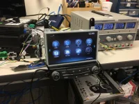
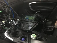
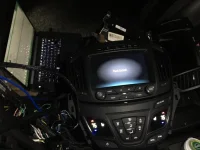
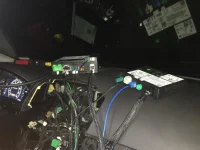
Incase you haven't figured it out by now I ran my radar detector wire across the headliner, just tucked it in up there, then down the pillar and left all of the extra wire by the fuses behind the compartment. Also you can see my concealed display hanging in one of the pictures with the gauge cluster. Still need to tap into power and ground it for the radar install to be done! More pictures later..

Then reverse the process to put it all back together.

I found these instructions. It is a good place to start. The dash is going to come apart exactly like the 2011-13. I did not remove the ashtray compartment completely. I just removed the outer trim to gain access to the screws. I also did not remove the steering wheel cover. The trim along the bottom of the cluster will just pull forward once you remove the screws to gain access to the 2 cluster screws.

All of the screws are 7 mm. If I remember correctly there are 7 screws in total to remove.
 
Good to know what I'll be getting into, thanks.
 
Super early mule or pilot car... Yard was in Michigan I'm assuming? 😉

You nailed it!!

Last position for the nav was right outside of Detroit!


Hooked my harness and all the components into the car for the first time and I'll be dammed if it didn't fire right up, give me the Theft Lock, accept the programming from my snapon, and f*cking work!!! Hell yeah!! Guess I can read a wiring diagram after all 😛
 

Attachments

  • IMG_5595.webp
    IMG_5595.webp
    74.3 KB · Views: 106
  • IMG_5594.webp
    IMG_5594.webp
    41.8 KB · Views: 104
  • IMG_5593.JPG.webp
    IMG_5593.JPG.webp
    52.6 KB · Views: 105
  • IMG_5591.JPG.webp
    IMG_5591.JPG.webp
    40.1 KB · Views: 108
  • IMG_5592.JPG.webp
    IMG_5592.JPG.webp
    71.2 KB · Views: 103
Back
Top